Rotary Friction Welder Plastic Spin Welding Machine of Frictional Rotation Fusion Equipment for Nylon_PP_PE Circular/Round Parts
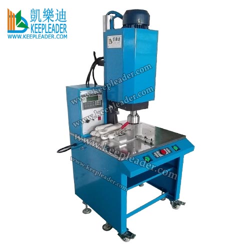
Rotary Friction Welder Plastic Spin Welding Machine
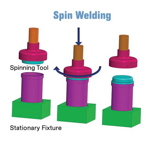
Rotary Friction Welder Plastic Spin Welding Machine includes rotating one parts, also named driving actuator in continuous circular motion against another fixed part, name fixture, under axial force, in all thermoplastic spin friction welding processes, the heat generated by the frictional action must be sufficient to melt and flow the plastic at the weld interface, sufficient heat is generated by a combination of welding time, welding force and interface velocity, determined by rotational motion
Product description
Rotary Friction Welder Plastic Spin Welding Machine
01: Parameter
Model | KLP-1500 |
Clutch power | 1500w |
Power Supply | AC 380V/50hz / 220V/60hz |
RPM | 3000r/min (60s*linear speed*Diameter*π) |
Cylinder | 63*75 |
Welding diameter | 160mm |
Driven motor | 2P |
Productivity | 1pc/2~3s |
Working mode | Top spinning |
Travel distance | 75mm |
Timing Control | 0~30s |
Precision | +/-0.5degree |
Welding pressure | 2~4.8mpa |
Axial press | 1mpa~6.9mpa |
Velocity | +10m/s |
Linear speed | 0.2~2m/s |
Gross Weight | 280kgs |
Landing Space | 750*675mm |
Overall size | 470*670*2000mm |
Packing volume | 1.6CBM |
02: Introduction of thermoplastic spin welder
The process of thermoplastic spin welder uses heat generated by rotational friction at the joint line to weld thermoplastic parts with rotationally symmetric joints, the thermoplastic spin welder applied pressure axially while rotating one part against its stationary mate, and the resulting generates heat that melts the parts together
03: Application
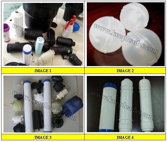
Thermoplastic spin welder can weld any circular plastic parts made out of thermoplastic, especially for Nylon, PP and Polyethylene Group, Water Filter, Cups, Cream Jar, Hair Oil Bottle, Container, Casserole, KEEPLEADER™ Technical team can work customized spindle and bottom fixture for various application
04: Thermoplastic spin welder process advantages
Ability to weld parts with a circular joint that are not easily welded by ultrasonic welder
Relatively fast cycle times when compared with other methods
Compatible with most thermoplastics
Ideal for welding of PP and PE materials
Ability to weld several dissimilar materials
No Consumables, fumes, or emissions
High strength, hermetic welds or typical
Heat confined to weld interface
Easily automated
Low cost, quick change tooling
Low maintenance
Low power consumption
05: Joint Design consideration
Thermoplastic part joint must be on a circular axis
Joint design should allow for adequate collapse distance
Final orientation of thermoplastic part if necessary
If at all possible the upper part would be designed for use with drive feature, place for upper tool grasp welding parts
The Joint area must be designed so that there is no other part contact interface
KEEPLEADER™ intelligent assembly solution offers no charge feasibility study and joint design review of your assembly
06: Control parameters
There are several primary process control parameters that affect weld quality, they are the surface velocity of the weld joint, press or axial speed, weld depth, and hold distance and time
07: Surface speed
For a fixed rotational spin speed (RPM), linear surface speed increases with weld joint diameter, for a fixed weld joint diameter, surface speed increases with motor RPM, smaller diameter thermoplastic parts therefore usually require more RPM than large parts of the same material, if the surface speed is too low, an adequate amount of heat will not generated to cause sufficient melting, if the speed is too high, excessive heat in the joint could result in material degradation or reduction in viscosity leading to material flow away from the joint
The selection of the proper surface speed depends to a large degree on the material and joint geometry of the thermoplastic parts being welded, some materials, such as PVC, can be readily welded for a wide range of values, while others require a narrow range, commonly quoted values in the literature recommend using +/- 2 m/sec (79 in. /sec.) as an initial testing value, this can be adjusted up or down depending on the results and part configuration
08: Press (Axial) speed
The press speed affects the amount of contact pressure between the parts being welded, which is required to generate friction heat, the large the speed, the larger rate of heat rise, in combination with the surface speed, press speed must be high enough to cause melting at the interface as opposed to grinding, but not too high as damage the parts, excess press speed can also lead to stalling of the spin motor as more torque is required to maintain constant spin speed
Selection of the optimum press speed depends on the material and joint geometry of the thermoplastic parts, as well as the surface speed, a range for initial experimentation is 0.5 to 2.0 mm/s
09: Welding depth
The determination of the proper weld depth is highly dependent on the application, the weld joint is typically designed for a specific weld penetration, ideally, the weld is sufficiently deep to produce a strong, hermetically sealed assembly, an excessive depth may lead to the formation of flash (materials that is ejected from the joint area during the weld and adheres to the assembly), the drawing out of reinforcing filler material and realignment of the interchain bonds in the weld plane resulting in a weak axial weld joint, and possibly part distortion
Since weld depth affects the joint strength and the amount of flash generated, it is important to design the weld joint properly to meet both requirements simultaneously, the incorporation of flash trap features is recommended to produce acceptable appearance without compromising strength.
10: Hold
During the hold phase, vertical press travel initially brings the molten parts closer together (dynamic hold) and then allows the molten material to solidify (static hold), amorphous plastic will normally take longer to solidify than semi crystalline plastic, the dynamic hold distance is typically a small value compared to the weld distance, an approximate staring point for initial application setup is 10% of weld distance, the static hold time can vary depending on the size of the part, but is usually in the 1~3 second range
Note:
Please tell us following information:
❶ The material and definite size of the product;
❷ 3D drawing if you have;
❸ It's better if you can send us the picture of workpieces or sample
Product uses
Rotary Friction Welder Plastic Spin Welding Machine is used to weld thermoplastic parts with rotational symmetrical joining surfaces, its joints must be circular, cylindrical, tubular, round and spherical shaped interface to apply rotational friction, the welding of the two halves in one part is due to the simultaneous application of rotation and axial pressure, thus, the friction obtained generates the heat necessary for their welding and fusing, Rotary Friction Welder Plastic Spin Welding Machine is ideal for PP, Nylon,PE,Polyester and any other semi-crystalline material which is much more difficulty to weld by ultrasonic, and its bonding result in air-tight and water-proof
Function illustration
Rotary Friction Welder Plastic Spin Welding Machine has simple process, but produce air-tight, water-proof joints, in 1st, the parts of the two halves are brought together and axial force is applied, the inter-facial friction begins but initially, no material flows, in 2nd, the welding zone material starts to melt and material displacement to the edge of the weld begins, in 3rd, the process is a steady state phase, the material is pushed out from the weld at a constant rate, in 4th, the process is the cooling phase when the inter-facial friction is stopped but the force is still applied to consolidate the active bonding, an alternative to welding by time is to weld by displacement, inter-facial friction is applied to components being welded until a fixed material displacement is achieved, this would typically 1 to 2mm, but would depend on the flatness of components being welded, undulation in the welding interface would need to be taken into consideration when setting the weld displacement
Contact Us
Rotary Friction Welder Plastic Spin Welding Machine must equip with custom spindle, also named driving actuator and holding device/pneumatic fixture, or named stationary base, whatever their shape and size are precision CNC machined, also add elastic rubber inside of cavity to apply axial pressure and downing displacement during rotational friction, our technical team will work with injection mold samples to work out a prototype for your confirmation prior to production, the cosmetic appearance after welding is also our endless pursuit, pls contact us for updated information
☺ Attn: MS Helen
✉ E-mail:sales@keepleader.com
☎ Cellphone: +86 13590415784 (Wechat/Whatsapp)
☎ Tel: +86 755 84190358
☞ Website: www.hfwelds.com / www.keepleader.com
Products
Search
ContactUs
ADD: Rongxing Bldg, Bulong rd, Bantian st, Longgang, Shenzhen 518129 P.R.China
ZIP: 518129
Contact: Ms Wang
Tel: +86-755-84190358
Fax: +86-755-84190358
Mob: +86-13590415784
Email: sales@keepleader.com

Welcome to visit our Factory!!!
Copyright ©2004-2026 ultrasonic cleaner,ultrasonic welder,high frequency welder,Ultrasonic golf Cleaner,High frequency packing machine,Vapor degreaser,Transparent Cylinder making machine,portable spot welders All Rights Reserved.
ADD: Rongxing Bldg, Bulong rd, Bantian st, Longgang, Shenzhen 518129 P.R.China ZIP: 518129 Contact: Ms Wang
Tel: +86-755-84190358 Fax: +86-755-84190358 Mob: +86-13590415784
Email: sales@keepleader.com 技术支持: keepleader


